- 您现在的位置:买卖IC网 > Sheet目录364 > SST49LF008A-33-4C-EIE-T (Microchip Technology)IC FLASH FWH 8MBIT 33MHZ 40TSOP
8 Mbit Firmware Hub
A Microchip Technology Company
SST49LF008A
Data Sheet
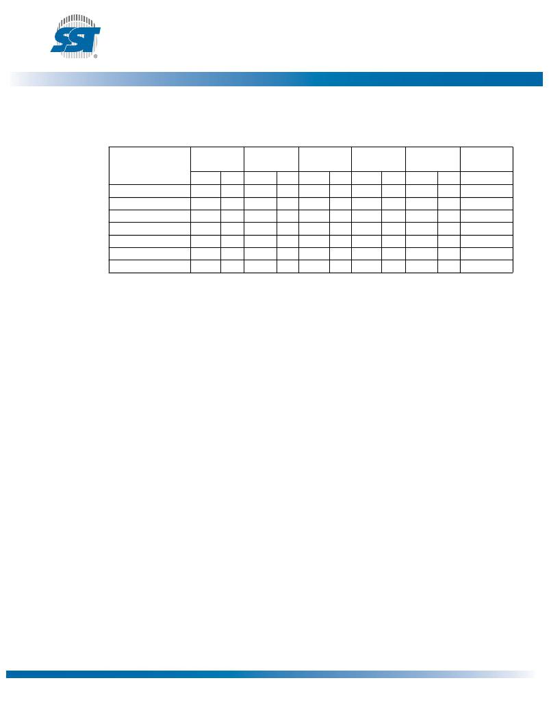
Software Command Sequence
Table 9: Software Command Sequence
Command
Sequence
1st 1
Write Cycle
2nd 1
Write Cycle
3rd 1
Write Cycle
4th 1
Write Cycle
5th 1
Write Cycle
6th 1
Write Cycle
Addr 2 Data Addr 2
Data Addr 2
Data Addr 2
Data Addr 2
Data Addr 2
Data
Byte-Program
5555H AAH 2AAAH 55H 5555H A0H
BA 3
Data
Sector-Erase
Block-Erase
5555H AAH 2AAAH 55H 5555H 80H 5555H AAH 2AAAH 55H
5555H AAH 2AAAH 55H 5555H 80H 5555H AAH 2AAAH 55H
SA X4
BA X5
30H
50H
Chip-Erase 6
Software ID Entry 7,8
5555H AAH 2AAAH 55H 5555H 80H 5555H AAH 2AAAH 55H 5555H 10H
5555H AAH 2AAAH 55H 5555H 90H
Software ID
Exit 9
XXH
F0H
Software ID Exit 9
5555H AAH 2AAAH 55H 5555H F0H
T9.6 25085
1. FWH Mode uses consecutive Write cycles to complete a command sequence; PP Mode uses consecutive bus cycles to
complete a command sequence.
2. Address format A 14 -A 0 (Hex), Addresses A 21 -A 15 can be V IL or V IH , but no other value, for the Command sequence in
PP Mode.
3. BA = Program Byte address
4. SA X for Sector-Erase Address
5. BA X for Block-Erase Address
6. Chip-Erase is supported in PP Mode only
7. SST Manufacturer’s ID = BFH, is read with A 0 =0,
With A 19 -A 1 = 0; 49LF008A Device ID = 5AH, is read with A 0 = 1.
8. The device does not remain in Software Product ID mode if powered down.
9. Both Software ID Exit operations are equivalent.
?2011 Silicon Storage Technology, Inc.
21
DS25085A
10/11
发布紧急采购,3分钟左右您将得到回复。
相关PDF资料
SST49LF016C-33-4C-EIE-T
IC FLASH SER LPC 16MBIT 40TSOP
SST49LF080A-33-4C-WHE-T
IC FLASH SER LPC 8MBIT 32TSOP
SST49LF160C-33-4C-NHE
IC FLASH SER LPC 16MBIT 32PLCC
ST40
DIAC 35-45V BILATERAL TRIG DO214
STRIKER
SURGE SUPPRESSR 120V 7OUT 6'CORD
SUPER-7
SURGE SUPPRESSOR 7 OUT 7' CORD
SUPER6TEL12
SURGE SUPPR 7OUT 12'CORD W/RJ11
SUPER6TEL
SURGE SUPPRESSOR 7OUT W/TEL
相关代理商/技术参数
SST49LF008A-33-4C-NH
制造商:SST 制造商全称:Silicon Storage Technology, Inc 功能描述:2 Mbit / 3 Mbit / 4 Mbit / 8 Mbit Firmware Hub
SST49LF008A-33-4C-NHE
功能描述:闪存 8M (1Mx8) 33MHz Commercial Temp RoHS:否 制造商:ON Semiconductor 数据总线宽度:1 bit 存储类型:Flash 存储容量:2 MB 结构:256 K x 8 定时类型: 接口类型:SPI 访问时间: 电源电压-最大:3.6 V 电源电压-最小:2.3 V 最大工作电流:15 mA 工作温度:- 40 C to + 85 C 安装风格:SMD/SMT 封装 / 箱体: 封装:Reel
SST49LF008A-33-4C-NHE_
制造商:Microchip Technology Inc 功能描述:
SST49LF008A-33-4C-NHE-T
功能描述:闪存 8M (1Mx8) 33MHz 3.0-3.6V Commercial RoHS:否 制造商:ON Semiconductor 数据总线宽度:1 bit 存储类型:Flash 存储容量:2 MB 结构:256 K x 8 定时类型: 接口类型:SPI 访问时间: 电源电压-最大:3.6 V 电源电压-最小:2.3 V 最大工作电流:15 mA 工作温度:- 40 C to + 85 C 安装风格:SMD/SMT 封装 / 箱体: 封装:Reel
SST49LF008A-33-4C-NHE-T-CUT TAPE
制造商:Microchip 功能描述:SST49LF Series 8 Mbit 1024 K x 8 3.3 V Firmware Hub - PLCC-32
SST49LF008A-33-4C-WH
制造商:SST 制造商全称:Silicon Storage Technology, Inc 功能描述:2 Mbit / 3 Mbit / 4 Mbit / 8 Mbit Firmware Hub
SST49LF008A-33-4C-WHE
功能描述:闪存 8 MBIT FIRMWARE HUB RoHS:否 制造商:ON Semiconductor 数据总线宽度:1 bit 存储类型:Flash 存储容量:2 MB 结构:256 K x 8 定时类型: 接口类型:SPI 访问时间: 电源电压-最大:3.6 V 电源电压-最小:2.3 V 最大工作电流:15 mA 工作温度:- 40 C to + 85 C 安装风格:SMD/SMT 封装 / 箱体: 封装:Reel
SST49LF008A-33-4C-WHE_
制造商:Microchip Technology Inc 功能描述:
